CBSE Previous Year Question Papers Class 12 Physics 2014 Outside Delhi Set-I
CBSE Previous Year Question Papers Class 12 Physics 2014 Outside Delhi Set-I
Question 1.
Using the concept of force between two infinitely long parallel current carrying conductors, define one ampere of current. [1]
Answer :
One ampere is the current which when flowing through each of the two parallel uniform long linear conductors placed in free space at a distance of one meter from each other will attract or repel each other with a force of 2 x 10⁻⁷ N per meter of their length.
Question 2.
To which part of the electromagnetic spectrum does a wave of frequency 5 x 10¹⁹ Hz belong ? [1]
Answer :
The frequency 5 x 10¹⁹ Hz lies in the gamma region of the electromagnetic spectrum.
Question 3.
What is the force between two small charges of 2 x 10⁻⁷ C and 3 x 10⁻⁷ C placed 30 cm apart in air? [1]
Answer: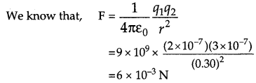
Question 4.
Define intensity of radiation on the basis of photon picture of light. Write its S J. unit. [1]
Answer :
The intensity of radiation can be defined as the energy associated with photons emitted from a unit surface area in unit time. Its S.I. unit is joule/metre2second (J/m2s).
Question 5.
The electric current flowing in a . wire in the direction from B to A is decreasing. Find out the direction of the induced current in the metallic loop kept above the wire as shown. [1]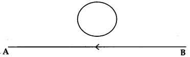
Answer:
The direction of the current in the loop will be such as to oppose the decrease of this field (Lenz’s Law).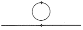
Question 6.
Why is it found experimentally difficult to detect neutrinos in nuclear β-decay ? [1]
Answer :
Neutrinos are difficult to detect experimentally in β-decay because these are uncharged particles with almost zero mass and also they interact weakly with matter.
Question 7.
Why is the use of A.C. voltage preferred over D.C. voltage ? Give two reasons. [1]
Answer :
The use of A.C. voltage is preferred over the use of D.C. voltage because of the following reasons:
- The energy losses while transmission of A.C. voltage are very less as compared to D.C. voltage.
- A.C. voltage can be controlled as required by using a transformer (i.e., stepped up or stepped down).
Question 8.
A biconvex lens made of a transparent material of refractive index 1.25 is immersed in water of refractive index 1.33. Will the lens behave as a converging or a diverging lens ? Give reason.[l]
Answer :
In this case the biconvex lens will behave as a diverging lens because the refractive index of water (1.33) is more than that of the material (1.25) of the lens.
Question 9.
Using Rutherford model of the atom, derive the expression for the total energy of the electron in hydrogen atom. What is the significance of total negative energy possessed by the electron ? [2]
OR
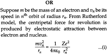
Using Bohr’s postulates of the atomic model, derive the expression for radius of nth electron orbit. Hence obtain the expression for Bohr’s radius.
Answer:
In a hydrogen atom, an electron having charge -e revolves around the nucleus having charge +e in a circular orbit of radius r.
Let,
Fc = Centripetal force required by the electron to move in circular orbit of radius r.
Fe= Electrostatic force of attraction between revolving electron and nucleus.
The electrostatic force of attraction (Fe.) provides the necessary centripetal force,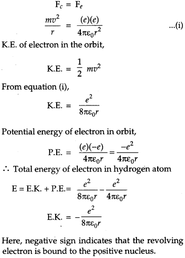
Question 10.
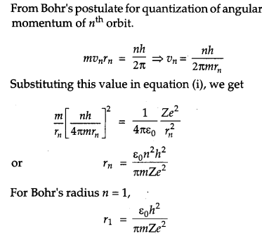
A parallel plate capacitor of capacitance C is charged to a potential V. It is then connected to another uncharged capacitor having the same capacitance. Find out the ratio of the energy stored in the combined system to that stored initially in the single capacitor. [2]
Answer :
Let ‘q’ be the charge on the charged capacitor.
Energy stored in it is,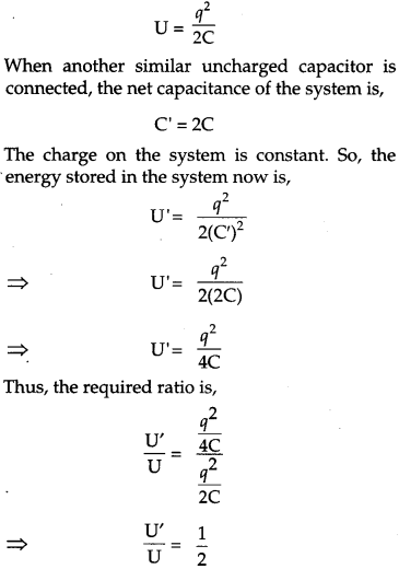
Question 11.
Considering the case of a parallel plate capacitor being charged, show how one is required to generalize Ampere’s circuital law to include the term due to displacement current [2]
Answer:
Gauss’ law states that the electric flux ΦE of a parallel plate capacitor having an area A, and a total charge Q is given by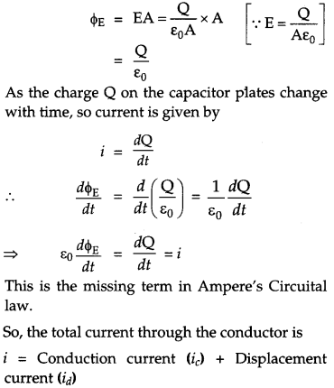
Question 12.
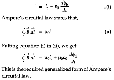
A cell of emf ‘E’ and internal resistance ‘r’ is connected across a variable resistor ‘R’. Plot a graph showing variation of terminal voltage ‘V’ of the cell versus the current I. Using the plot, show how the emf of the cell and its internal resistance can be determined. [2]
Answer :
The terminal voltage ‘V’ of the cell is given by
V = E – Ir
where E is the emf of the cell,
r is the internal resistance of the cell and,
I is the current through the circuit.
Comparing with the equation of a straight line y = mx + c, we get
y = V; x = I m = -r ; c = E
Graph showing variation of terminal voltage ‘V’ of the cell versus the current ‘I’.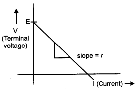
Emf of the cell = Intercept on V axis.
Internal resistance = slope of the line.
Question 13.
Explain, with the help of a circuit diagram, the working of a p-n junction diode as a half-wave rectifier. [2]
Answer :
The circuit diagram for a p-n junction diode as a half wave rectifier is shown below :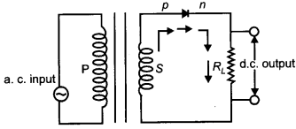
Working : During the positive half cycle of the input a.c., the p-n junction is forward biased i.e., the forward current flows from p to n. In the forward biasing, the diode provides a very low resistance and allows the current to flow. Thus, we get output across load.
During the negative half cycle of the input a.c., the p-n junction is reversed biased. In the reverse biasing, the diode provides a high resistance and hence a very small amount of current will flow through the diode which is of negligible amount. Thus no output is obtained across the load. During the next half cycle, output is again obtained as the junction diode gets forward biased. Thus, a half wave rectifier gives discontinuous and pulsating d.c. output across the load resistance.
The waveform of input and output is shown below: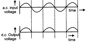
Question 14.
Estimate the average drift speed of conduction electrons in a copper wire of cross-sectional area 1.0×10⁻⁷ m2 carrying a current of 1.5 A. Assume the density of conduction electrons to be 9 x 1028 m-3. [2]
Answer:
Since, drift velocity,
vd=InAq
Where,
I is the current,
n is the charge density,
q is charge of the electron, and
A is cross-sectional area.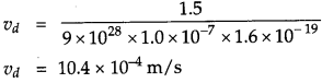
Question 15.
Two monochromatic rays of light are incident normally on the face AB of an isosceles rightangled prism ABC. The refractive indices of the glass prism for the two rays ‘1’ and ‘2’ are respectively 1.35 and 1.45. Trace the path of these rays after entering through the prism. [2]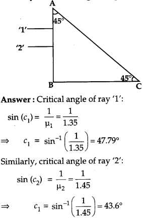
Ray ‘1′ and ‘2’ will fall on the side AC at an angle of incidence (i) of 45°. Critical angle of ray ‘1’ is greater than i, so it will get refracted from the prism. Critical angle of ray ‘2’ is less than that of i, so it will undergo total internal reflection.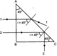
Question 16.
Write the functions of the following in communication systems : [2]
(i) Transducer
(ii) Repeater
Question 17.
Show diagrammatically the behavior of magnetic field lines in the presence of
(i) para magnetic and
(ii) diamagnetic substances. How does one explain this distinguishing feature ? [2]
Answer:
(i) The behavior of magnetic field lines in the presence of a para magnetic substance is shown below: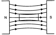
(ii) The behavior of magnetic field lines in the presence of a diamagnetic substance is shown below: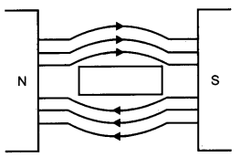
This distinguishing feature is because of the difference in their relative permeability. The relative permeability of diamagnetic substance is less than 1, so the magnetic lines of force do not prefer passing through the substance whereas the relative permeability of a paramagnetic substance is greater than 1, so the magnetic lines of force prefer passing through the substance.
Question 18.
Draw a circuit diagram of n-p-n transistor amplifier in CE configuration. Under what condition does the transistor act as an amplifier? [2]
Question 19.
(a)Using the phenomenon of polarization, show how transverse nature of light can be demonstrated.
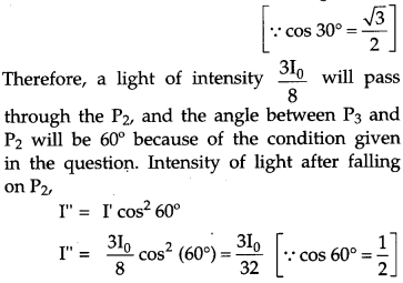
(b) Two polaroids P1and P2 are placed with their pass axes perpendicular to each other. Unpolarised light of intensity I0 is incident on P1. A third polaroid P3 is kept in between P1 and P2 such that its pass axis makes an angle of 30° with that of P1. Determine the intensity of light transmitted through P1, P2 and P3. [3]
Answer :
(a) Suppose that an ordinary light is incident normally on a pair of crystals C1 and C2. When the incident ray of light passes through crystal C1 it gets plane polarised in the direction perpendicular to the length of crystal. Now, we see that when the axis of two crystals are parallel, the intensity of the emerging light will be maximum. When the second crystal is placed perpendicular with respect to the first crystal, the intensity of light observed is zero. This is due to the electric field of the plane polarised light obtained from C1 can vibrate only in one direction. Hence, when the axis of the crystal C2 is perpendicular to its direction of vibration of electric field, it gets blocked. This shows the transverse nature of light.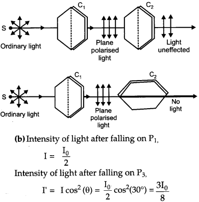
Question 20.
Define the term ‘mutual inductance’ between the two coils. Obtain the expression for mutual inductance of a pair of long coaxial solenoids each of length l and radii r1 and r2 (r2 >>r1). Total number of turns in the two solenoids are N1 and N2 respectively.
Answer:
Mutual inductance of two coils is equal to the e.m.f. induced in one coil when rate of change of current through the other coil is unity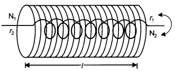
Mutual inductance of two co-axial solenoids : Consider two long co-axial solenoid each of length l with number of turns N1 and N2 wound one over the other. Number of turns per unit
length in solenoid, n=N1l. If I1 is the current flowing in primary solenoid, the magnetic field produced within this solenoid.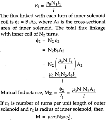
Question 21.
Answer the following: [3]
(a) Why are the connections between the resistors in a meter bridge made of thick copper strips ?
(b) Why is it generally preferred to obtain the balance point in the middle of the meter bridge wire ?
(c) Which material is used for the meter bridge wire and why ?
OR
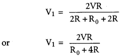
A resistance of R Q draws current from a potentiometer as shown in the figure. The potentio meter has a total resistance R0 Ω.
A voltage V is supplied to the potentiometer. Derive an expression for the voltage across R when the sliding contact is in the middle of the potentiometer.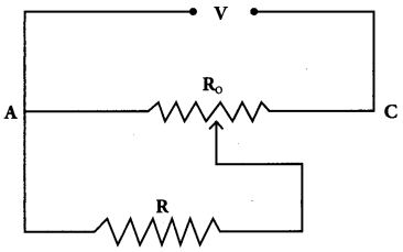
Answer: (a) The connection between the resistors in a meter bridge is made of thick copper strips because the resistivity of a copper wire is very low. As, the connections are thick, so the area becomes large and the resistance of the wires becomes almost negligible.
(b) It is preferred to obtain the balance point in the middle of the meter bridge wire because it improves the sensitivity of the meter bridge.
(c) Constantan is used for meter bridge wire because its temperature coefficient of resistance is almost negligible due to which the resistance of the wire does not get affected on increasing temperature of the wire due to flow of current.
OR
As the slide is in the middle of the potentiometer so, only half of its resistance (R0 /2) will be in parallel with the resistance R. Hence, the total resistance (R1) will be given by the following expression: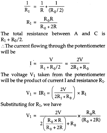
Question 22.
A convex lens of focal length 20 cm is placed co axially with a convex mirror of radius of curvature 20 cm. The two are kept at 15 cm apart from each other. A point object lies 60 cm in front of the convex lens. Draw a ray diagram to show the formation of the image by the combination. Determine the nature and position of the image formed. [3]
Answer:
Let us first locate the image of the point object O formed by the convex lens.
Here : u = -60 cm and f= 20 cm
From the lens formula, we have :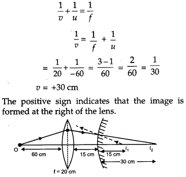
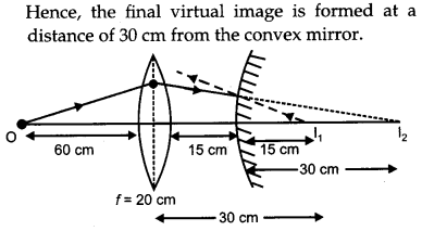
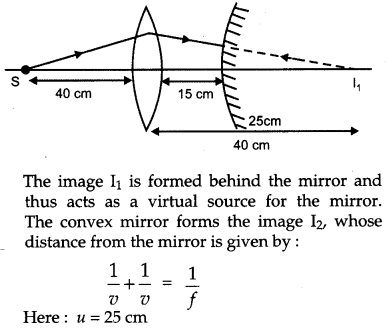
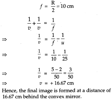
The image I1 is formed behind the mirror and acts as a virtual oject for the mirror. The convex mirror forms the image I2, whose distance from the mirror can be determined as :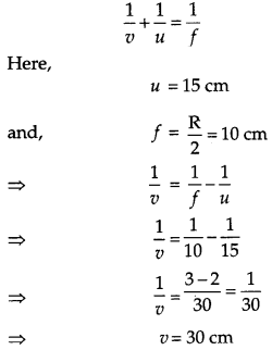
Question 23.
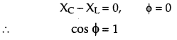
A voltage V = V0 sin ωt is applied to a series LCR circuit. Derive the expression for the average power dissipated over a cycle. Under what condition is
(i) no power dissipated even though the current flows through the circuit,
(ii) maximum power dissipated in the circuit ? [3]
Answer :
Voltage V = V0 sin ωt is applied to a series LCR circuit.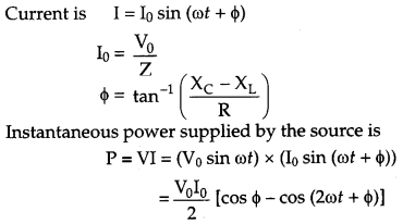
The average power over a cycle is average of the two terms on the R.H.S. of the above equation. The second term is time dependent, so, its average is zero.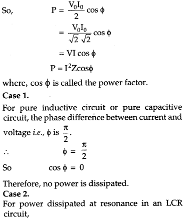
Question 24.
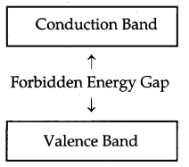
Write any two distinguishing features between conductors, semiconductors and insulators on the basis of energy band diagrams. [3]
Answer:
Conductors:
- In case of conductors, the valence band is completely filled and the conduction band can have two cases-either it is partially filled with an extremely small energy gap between the valence and conduction bands or it is empty, with the two bands overlapping each other as
shown below:
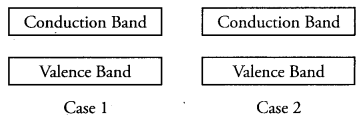
- Even when a small current is applied, conductors can conduct electricity.
Insulators:
- In case of insulators, the energy gap between the conduction and valence bands is very large and the conduction band is practically empty.
- When an electric field is applied to a semiconductor, the electrons in the valence band find it relatively easier to jump to the conduction band. So, the conductivity of semiconductors lies between the conductivity of conductors and insulators.
Semiconductors:
- In case of semiconductor, the energy band structure of semiconductors is similar to insulators, But in this case, the size of forbidden energy gap is quite smaller than that of the insulators.
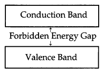
- When an electric field is applied to a semiconductor, the electrons in the valence band find it relatively easier to jump to the conduction band. So, the conductivity of semiconductors lies between the conductivity of conductors and insulators.
Question 25.
For the past some time, Aarti had been observing some erratic body movement, unsteadiness and lack of coordination in the activities of her sister Radha, who also used to complain of severe headache occasionally. Aarti suggested to her parents to get a medical check-up of Radha. The doctor thoroughly examined Radha and diagnosed that she has a brain tumor. [3]
(a) What, according to you, are the values displayed by Aarti?
(b) How can radioisotopes help a doctor to diagnose brain tumor ?
Answer:
(b) A little amount of radioisotope like radio iodine is inserted into the body along with organic dyes which are absorbed strongly by the tumor tissue than the normal tissues. By detecting the emitted radiation, the radiologist get information about the size and location of the tumor.
Question 26.
Write two basic modes of communication. Explain the process of amplitude modulation. Draw a schematic sketch showing how amplitude modulated signal is obtained by superposing a modulating signal over a sinusoidal carrier wave. [3]
Question 27.
An electron microscope uses electrons accelerated by a voltage of 50 kV. Determine the de-Broglie wavelength associated with the electrons. Taking other factors, such as numerical aperture etc., to be same, how does the resolving power of an electron microscope compare with that of an optical microscope which used yellow light ? [3]
Answer :
The de-Broglie wavelength of the electrons is given by :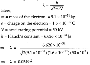
Resolving power of a microscope, R=2μsinθλ
This formula shows that to enhance resolution, we have to use shorter wavelength and media with large indices of refraction.
For an electron microscope, μ is equal to 1 (vacuum). For an electron microscope, the electrons are accelerated through a 60,000 V potential difference.
Thus, the wavelength of electrons is given by,
λ=12.27V√=12.2760000√=0.05A
As, λ is very little (roughly 10-5 times smaller) for electron microscope than an optical microscope which uses yellow light of wavelength (5700 A to 5900 A). So, the resolving power of electron microscope is about 105 greater than that of optical microscope.
Question 28.
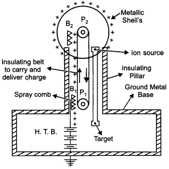
Draw a labelled diagram of Van de Graaff generator. State its working principle to show how by introducing a small charged sphere into a larger sphere, a large amount of charge can be transferred to the outer sphere. State the use of this machine and also point out its limitations. [5]
OR
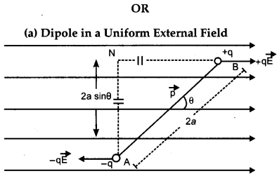
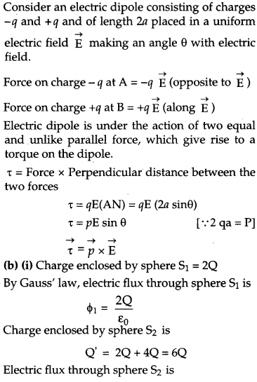
(a) Deduce the expression for the torque acting on a dipole of dipole moment p⃗ in the presence of a uniform electric field E⃗ .
(b) Consider two hollow concentric spheres, S1 and S2, enclosing charges 2Q and 4Q respectively as shown in the figure,
(i) Find out the ratio of the electric flux through them, ‘
(ii) How will the electric flux through the sphere S1 change if a medium of dielectric constant ∈r ,’∈r‘ is introduced in the space inside S1 in place of air ?
Deduce the necessary expression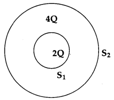
Answer :
Van de Graaff generator is a device used for building up high potential differences of the order of a few million volts.
Principle : The working of Van de Graaff generator is based on the following two electrostatic phenomena.
- Discharging action at sharp points (corona discharge) i.e., electric discharge takes place in air or gases readily at the pointed ends of conductors.
- If a charged conductor is brought into internal contact with a hollow conductor, all of its charge transfers to the hollow conductor, howsoever high the potential of the latter may be.
Construction : It has a big spherical conducting shell (S) kept over insulating pillars. A long narrow insulating belt is wound around two pulleys P1 and P2. B1 and B2 are two metal combs with sharp points. B1 is known as spray comb and B2 collecting comb.
Working : The spray comb provides positive potential by high tension source. The positive charge is sprayed on belt.
As belt moves and touches the sphere, a negative charge is induced on the sharp ends of collecting comb B2 and similar positive charge is induced on the further end of B2. This positive charge moves immediately to the outer surface of S, because of discharging action of sharp points of B2, the positive charge on the belt is neutralized. The uncharged belt moves downwards and collects the positive charge from B1, which is then collected by B2. This process is repeated and the positive charge on S goes on accumulating. In this way, voltage differences of as much as 6 or 8 million volts (with respect to the ground) can be created.
Use : Van de Graaff generator is used to create high potential differences that are used to accelerate charged particles such as electrons, protons, ions, etc., used for nuclear reactions.
Limitations:
- It is a series of combination that allows only one way for moving charge.
- It can accelerate only the charged particles and not the uncharged particles.

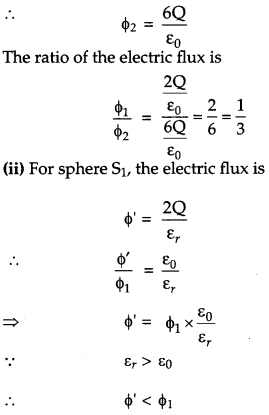
Therefore, the electric flux through the sphere S1 decreases with the introduction of the dielectric inside it.
Question 29.
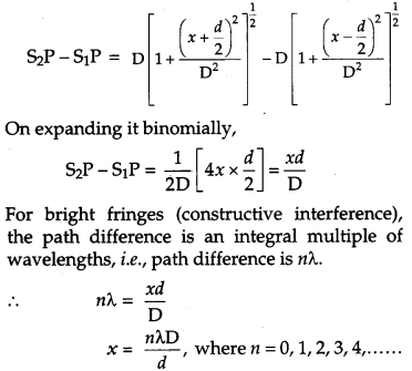
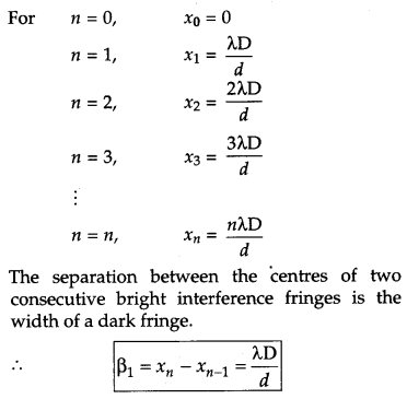
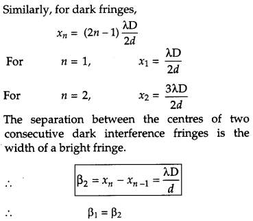
(a) In Young’s double slit experiment, describe briefly how bright and dark fringes are obtained on the screen kept in front of a double slit. Hence obtain the expression for the fringe width.
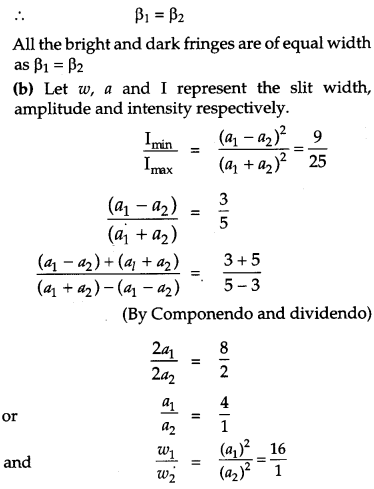
(b) The ratio of the intensities at minima to the maxima in the Young’s double slit experiment is 9 : 25. Find the ratio of the widths of the two slits. [5]
OR
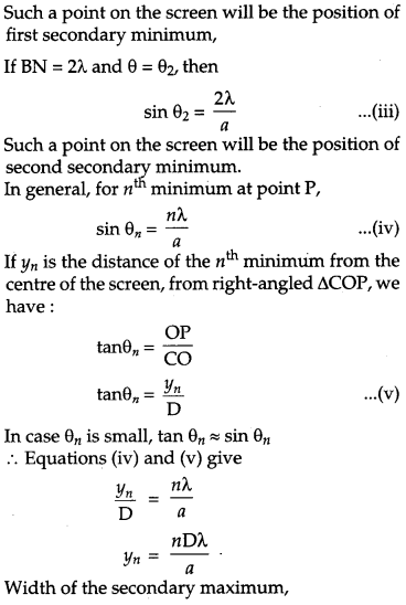
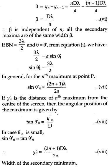
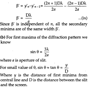
(a) Describe briefly how a diffraction pattern is obtained on a screen due to a single narrow slit illuminated by a monochromatic source of light. Hence obtain the conditions for the angular width of secondary maxima and secondary minima.
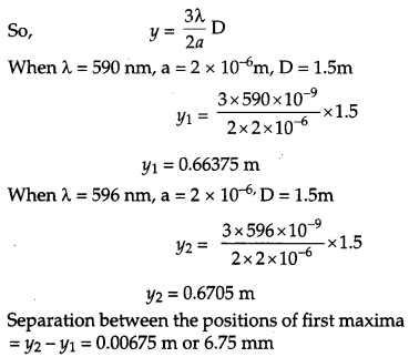
(b) Two wavelengths of sodium light of 590 nm and 596 nm are used in turn to study the diffraction taking place at a single slit of aperture 2 x 10⁻⁵ m. The distance between the slit and the screen is 1.5 m. Calculate the separation between the positions of first maxima of the diffraction pattern obtained in the two cases.
Answer :
(a) In Young’s double slit experiment, the wave fronts from the two illuminated slits supere mpose on the screen. This results in formation of alternate bright and dark fringes because of constructive and destructive interference, respectively. The intensity of light is maximum at the center C of the screen and it is called central maxima.
Let S1 and S2 be two slits separated by a distance d. GG’ is the screen at a distance D from the slits S1 and S2. Both the slits are equidistant from point C. The intensity of light will be maximum at this point due to the path difference of the waves reaching this point will be zero. At point P, the path difference between the rays coming from the slits S1 and S2 is S2P – S1P.
Now, S1S2 = d, EF = d, and S2F = D
∴ In ΔS1PF,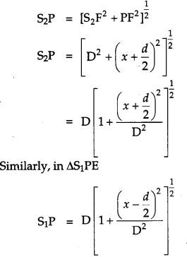
OR
(a) The phenomenon of bending of light round the sharp comers of an obstacle and spreading into the regions of the geometrical shadow is called diffraction.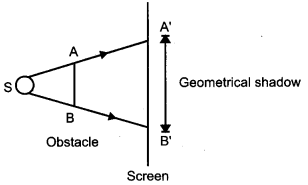
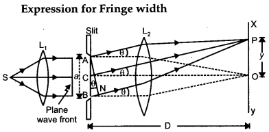
Consider a parallel light beam from a lens is incident on slit AB. As diffraction happens, the pattern is focussed on screen XY with the help of lens L2. We will get a diffraction pattern that is a central maximum at the centre O flanked by a number of dark and bright fringes known as secondary maxima and minima.
Central Maximum : Each point on the plane wave front AB sends secondary wavelets in all directions. The waves from points equidistant from the center C kept on the upper and lower half reach point O with zero path difference and so, reinforce each other, making maximum intensity at point O.
Positions and Widths of Secondary Maxima and Minima:
Consider a point P on screen at which wavelets moving in a direction making angle θ with CO are brought to focus by the lens. The wavelets from points A and B will have a path difference similar to BN: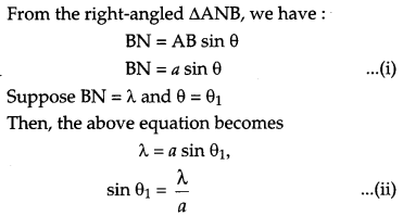
Question 30.
(a) Deduce an expression for the frequency of revolution of a charged particle in a magnetic field and show that it is independent of velocity or energy of the particle.
(b) Draw a schematic sketch of a cyclotron. Explain, giving the essential details of its construction, how it is used to accelerate the charged particles. [5]
OR
(a) Draw a labelled diagram of a moving coil galvanometer. Describe briefly its principle and working.
(b) Answer the following:
(i) Why is it necessary to introduce a cylindrical soft iron core inside the coil of a galvanometer.
(ii) Increasing the current sensitivity of a galvanometer may not necessarily increase its voltage sensitivity. Explain, giving reason.
Answer :
(a) When a charged particle having charge q moves inside a magnetic field B→ having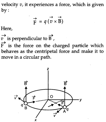
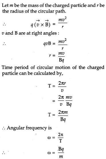
Therefore, the frequency of the revolution of the charged particle is independent of the velocity or the energy of the particle.
(b) The working principle of a cyclotron is that a charge particle can be accelerated to high energy by an oscillating electric field.
A cyclotron uses an electric field to accelerate charge particles across the gap between the two D-shaped magnetic field regions. The magnetic field is perpendicular to the paths of the charged particles that makes them follow in circular paths within the two Ds. Each time the charged particles cross the Ds, it is accelerated by an alternating voltage. As its speed increases the radius of path of each particle also increases. So, the accelerated particles move in a spiral path to the other wall of the cyclotron.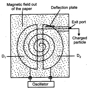
Square wave electric fields are used to accelerate the charged particles in a cyclotron.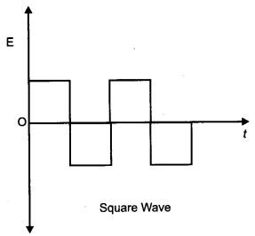
At the time the charge particle finishes its half circle, the accelerating electric field reverse so that it gets accelerated across the gap between the Ds.
The particle gets accelerated again and again, and its velocity increases. Therefore, a high kinetic energy is achieved.
OR
(a) Moving coil galvanometer : It is a device used for detecting and measuring small electric current.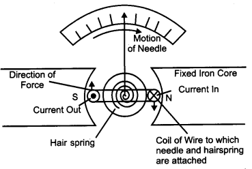
Principle : The working is based upon the principle, when a current carrying coil suspended in a magnetic field experiences a torque.
Construction : It consists of a coil with a large number of turns of insulated copper wire wounded on a metallic frame. The coil is suspended by means of a phosphor bronze strip and a horse shoe magnet’s NS surrounds it. The lower end of the coil is attached with a hair spring. The scale of the pointer is attached to the other end of the spring.
Working : When current is passed, the couple acts on it. Since the plane remains parallel to the magnetic field in all position of the coil, the force on the vertical arms always remains perpendicular to the place of the coil.
Let I = the current flowing through coil,
B = magnetic field supposed to be uniformed and always parallel to the coil, and
A = area of the coil.
Deflection acting on the coil is
T = NIBA sin 90° – NIBA [ ∵ sin 90° = 1]
Due to the deflection torque, the coil rotates and suspended wire gets twisted. The suspension fiber experiences a restoring torque. If Φ is angle through the coil rotates and k is the restoring torque per unit angular twist, then
Restoring torque, T = kΦ
In equilibrium, Deflection torque = Restoring torque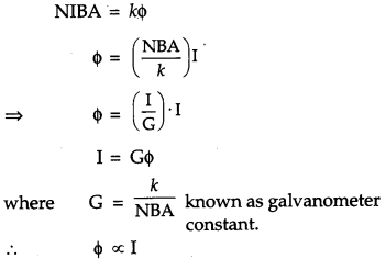
This provides a linear scale for the galvanometer,
(b) (i) When a soft iron core is used the magnetic field lines tend to crowd through the core. It is because, soft iron core is ferromagnetic in nature. As a result, the strength of the magnetic field due to the field magnet increases, which in turn increases the sensitivity of the galvanometer.
(ii) Current sensitivity of a galvanometer is defined as the deflection produced in the galvanometer when a unit current flows through it.
Is=θI=nBAK …….. (i)
Voltage sensitivity of a galvanometer is defined as the deflection produced in the galvanometer when a unit voltage is applied across two terminals.
Vs=θV=θIR=nBAKR=IsR…(ii)
Where n = number of turns in the coil of galvanometer
B = Magnetic field around coil
A = Area of coil
K = restoring torque per unit twist
From equation (i) we can say that- current sensitivity increases by increasing n, B, A and decreases by decreasing K.
From equation (ii) we can say that voltage sensitivity increases by increasing n, B, A and decreases by decreasing K, R.
In case of current sensitivity if we increases the no. of turns n its current sensitivity ‘ increases. Since resistance of galvanometer R also increases, voltage sensitivity remains same or unchanged. Therefore increase in current sensitivity of galvanometer may not necessarily increase the voltage
CBSE Previous Year Question Papers Class 12 Physics 2014 Outside Delhi Set-II
Note : Except for the following questions, all the remaining questions have been asked in previous Set.
Question 1.
A conducting loop is held above a current carrying wire PQ’ as shown in the figure. Depict the direction of the current induced in the loop when the current in the wire PQ is constantly increasing. [1]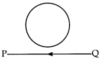
Answer:
Anticlockwise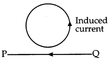
Question 2.
Why do the electrostatic field lines not form closed loops ? [1]
Answer :
The electrostatic field lines originate from positive charge and end at the negative charge. As the isolated positive and negative charge do exist, the electrostatic field lines do not form closed loops.
Question 3.
A biconvex lens made of a transparent material of refractive index 1.5 is immersed in water of refractive index 1.33. Will the lens behave as a converging or a diverging lens ? Give reason. [1]
Answer:
The refractive index of material of lens (1.5) is greater than the refractive index of water (1.33). So, it will behave as a converging lens.
Question 4.
To which part of the electromagnetic spectrum does a wave of frequency 3 x 10 13 Hz belong ? [2]
Answer :
The frequency 3 x 10 13 Hz belongs to infrared region, of electromagnetic spectrum.
Question 5.
Estimate the average drift speed of conduction electrons in a copper wire of cross-sectional area 2.5 x 10 -7 m2 carrying a current of 1.8 A. Assume the density of conduction electrons to be 9 x 1028 m-3. [2]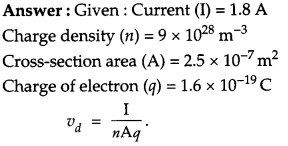
Question 6.
Write the functions of the following in communication systems : [3]
(i) Transmitter
(ii) Modulator
Question 7.
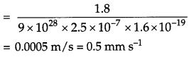
(a) Show with the help of a diagram, how unpolarised sunlight gets polarized due to scattering.
(b) Two Polaroids P1 and P2 are placed with their pass axes perpendicular to each other. Unpolarised light of intensity I0 is incident on P1. A third polaroid P3 is kept in between P1 and P2 such that its pass axis makes an angle of 45° with that of P1. Determine the intensity of light transmitted through P1, P2 and P3. [3]
Answer:
(a) The given figure shows, the incident sunlight is unpolarised. The dots stand for polarisation perpendicular to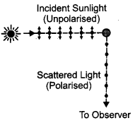
the plane of the figure. The double arrows show polarisation in the plane of the figure. Under the influence of the electric field of the incident wave the electrons in the molecules acquire components of motion in both these directions. We have drawn an observer looking at 90° to the direction of the sun. Clearly, charges accelerating parallel to the double arrows do not radiate energy towards this observer since their acceleration has no transverse component. The radiation scattered by the molecule is therefore represented by dots. It is polarised perpendicular to the plane of the figure. This explains the polarisation of scattered light from the sky.
b) As given in the question, the polaroids Pi and P2 are placed with their pass axes perpendicular to each other. Also, P3 is placed at an angle of 45° . with respect to P1.
Now, we have:
Intensity of light after falling on P1, I = I0 /2
Intensity of light after falling on P3,
I=Icos2θ=I02cos245∘=I04
Therefore, a light of intensity I0/4 will pass through P3 and the angle between P3 and P2 will be 45° because of the condition given in the question.
Intensity of light after falling on P2,
I′′=I′cos2(θ)=I04cos245∘=I08
Question 8.
Define the term self-inductance of a solenoid. Obtain the expression for the magnetic energy stored in an inductor of self-inductance L to build up a current I through it. [3]
Answer :
The ratio of magnetic flux through the solenoid to the current passing through it is called self-inductance of a solenoid. It is given by
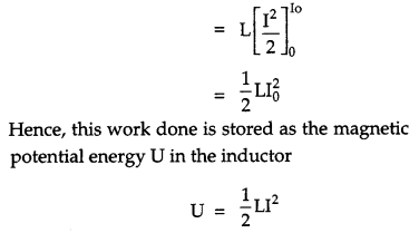
Energy stored in an inductor : When a current grows through an inductor, a back e.m.f. is set up which opposes the growth of current. So work needs to be done against back e.m.f. (e) in building up the current. This work done is stored as magnetic potential energy.
Let I be the current through the inductor L at any instant t. The current rises at the rate dl/dt.
So the induced e.m.f. is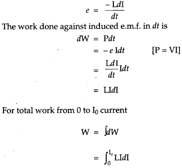
Question 9.
A convex lens of focal length 20 cm is placed co axially with a concave mirror of focal length 10 cm at a distance of 50 cm apart from each other. A beam of light coming parallel to the principal axis is incident on the convex lens. Find the position of the final image formed by this combination. Draw the ray diagram showing the formation of the image. [5]
Answer:
The beam incident on lens L is parallel to principal axis. Hence the lens forms an image I1 at its focus, i.e., at a distance OI1 (= 20 cm) from the lens.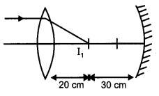
The image I1 is formed in front of the mirror and hence, acts as a real source for the mirror. The concave mirror forms the image I2, whose distance from the mirror can be calculated as;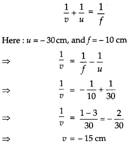
Hence, the final image is formed at a distance of 15 cm from the concave mirror, as shown in the following figure.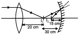
CBSE Previous Year Question Papers Class 12 Physics 2014 Outside Delhi Set-III
Note : Except for the following questions, all the remaining questions have been asked in previous Sets.
Question 1.
A conducting loop is held below a current carrying wire PQ as shown. Predict the direction of the induced current in the loop when the current in the wire is constantly increasing. [1]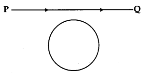
Answer:
Anticlock wise direction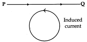
Question 2.
The graph shows variation of stopping potential V0 versus frequency of incident radiation v for two photosensitive metals A and B. Which of the two metals has higher threshold frequency and why ? [1]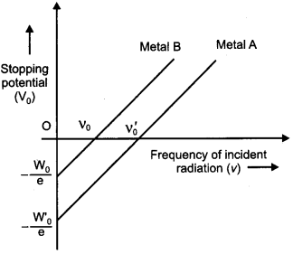
Answer :
Metal A has higher threshold frequency because from the graph it is clear that the minimum frequency required to start photo emission is more in A than that of B.
Question 3.
Why do the electric field lines never cross each other ? [1]
Answer:
At any point, if electric field lines cross each other than two tangents can be drawn, it means at that point there are two directions of electric field, which is impossible.
Question 4.
To which part of the electromagnetic spectrum does a wave of frequency 5 x 10¹¹ Hz belong ? [2]
Answer :
A wave of frequency 5 x 10¹¹ Hz will belong to the microwaves of electromagnetic spectrum.
Question 5.
Estimate the average drift speed of conduction electrons in a copper wire of cross-sectional area 2.5 × 10⁻⁷ m2 carrying a current of 2.7 A. Assume the density of conduction electrons to be 9 × 1028 m-3. [2]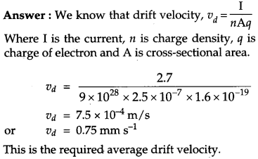
Question 6.
Write the functions of the following in communication systems : [3]
(i) Receiver
(ii) Demodulator
curvature 20 cm. The two are kept at 15 cm from each other. A point object placed 40 cm in front of the convex lens. Find the position of the image formed by this combination. Draw a ray diagram to show the formation. [3]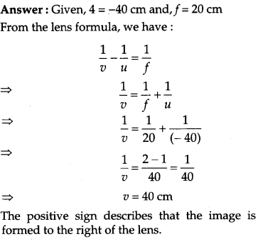
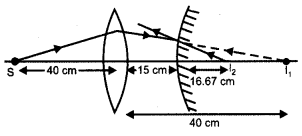
Question 7.
(a) A rod of length ‘l’ is moved horizontally with a uniform velocity V in a direction perpendicular to its length through a region in which a uniform magnetic field is acting vertically downward. Derive the expression for the emf induced across the ends of the rod.
(b) How does one understand this motional emf by involving the Lorentz force acting on the free charge carriers of the conductor ? Explain. [5]
Answer :
(a) Consider a rod PQ of length l moving in a magnetic field B→ with a constant velocity v→. The length of the rod is perpendicular to the magnetic field and also the velocity is perpendicular to both the rod and field. The free electrons of the rod also move at this velocity \overrightarrow{\mathrm{v}} because of which it experiences a magnetic force.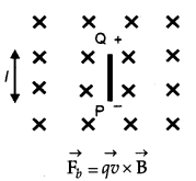
This force is towards Q to P.
Thus, the free electrons will move towards P and positive charge will appears at Q. An electrostatic field E is developed within the wire from Q to P. This field exerts a force.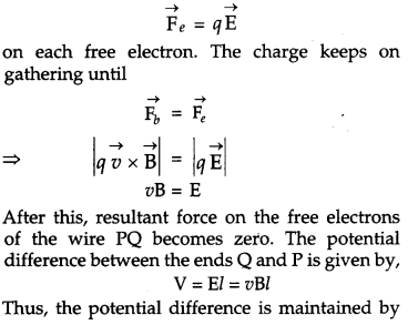
the magnetic force on the moving free electron and hence, produces an emf, e = Bvl
(b) Lorentz force acting on a charge q which is moving with a speed v in a (normal) uniform magnetic field B, is Bqv.
All the charges will experience the same force. Work done to move the charge from P to Q,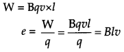
Question 8.
(a) Show, giving via suitable diagram, how unpolarized light can be polarized by reflection.
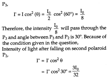
(b) Two Polaroids P1 and P2 are placed with their pass axes perpendicular to each other. Unpolarised light of intensity I0 is incident on P1. A third polaroid P3 is kept in between P1 and P2 such that its pass axis makes an angle of 60° with that of P1. Determine the intensity of light transmitted through P1, P2 and P3. [5]
Answer :
(a) On reflection from a transparent medium a normal light beam becomes partially polarised. As the angle of incidence gets higher, the degree of polarization gets higher.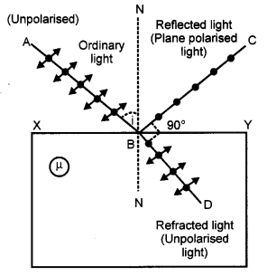
The reflected light beam becomes fully polarised at a certain angle. This angle of incidence is known as polarizing angle (p).
At the interface of a refracting medium when light is incident at polarizing angle, the refractive index of the medium is similar to the tangent of the polarizing angle.
µ = tan p
where
µ → Refractive index of the refracting medium
p → Polarising angle
(b) As given, the polaroid P1 and P2 are placed with their axes perpendicular to each other and polaroid P3 placed at 60° with respect to P1